The response of the IRGA is calibrated by comparison to ambient CO![]() and H
and H![]() O measurements from the slow-response sensors, similar to the
method of Berger et al. (2001) (i.e. no calibration gases are used in the fast
response system). A calibrated CO
O measurements from the slow-response sensors, similar to the
method of Berger et al. (2001) (i.e. no calibration gases are used in the fast
response system). A calibrated CO![]() measurement is typically obtained
every 8 minutes at the 82 m level. Exact synchronization of the signals requires
accounting for the time for air to pass through the sampling tubes of the profile
and the eddy systems.
measurement is typically obtained
every 8 minutes at the 82 m level. Exact synchronization of the signals requires
accounting for the time for air to pass through the sampling tubes of the profile
and the eddy systems.
The lag time of the profile system is calculated from the measured flow rates and from in situ tests. The lag time for the profiling system was around 3 minutes.
It is very important to keep track of the lag times since these values are also
used during the calculation of the lagged covariances, which appear to be very
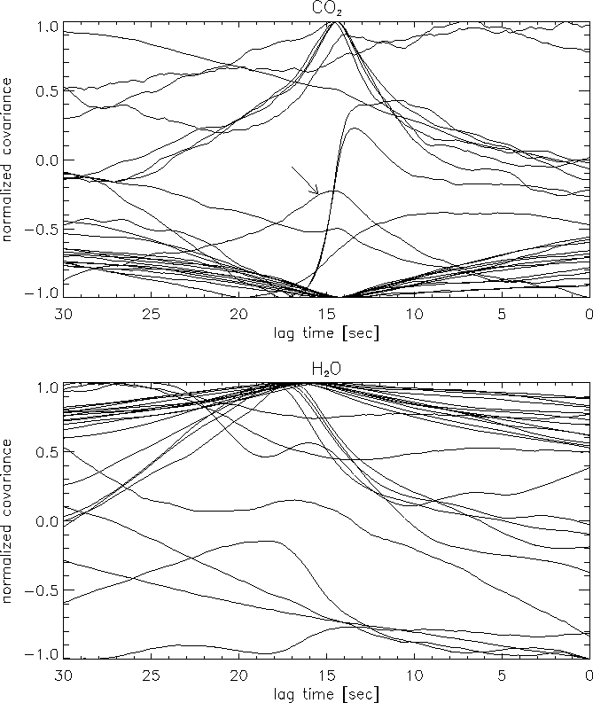
sensitive for the lag times in some cases. For the eddy covariance system two
different lag time values are calculated for H![]() O and CO
O and CO![]() (Moncrieff et al., 1997) using a spectral method. First, the daily lag time
values are calculated without any restrictions for the whole dataset. Then a
polynomial is fitted to the long-term lag time series which is used to determine
the actual time window where the lag time is supposed to occur. The time window
used is 16 sec around the fitted value. Lagged covariances inside this window
are used for the following procedure.
(Moncrieff et al., 1997) using a spectral method. First, the daily lag time
values are calculated without any restrictions for the whole dataset. Then a
polynomial is fitted to the long-term lag time series which is used to determine
the actual time window where the lag time is supposed to occur. The time window
used is 16 sec around the fitted value. Lagged covariances inside this window
are used for the following procedure.
The usual method is to calculate the lag times for each averaging period to search for the time where the maximum correlation occurs (Fan et al., 1990).

|
The method described above for CO![]() is not always applicable for H
is not always applicable for H![]() O.
The nighttime lag values are usually undetectable since latent heat flux is
very small during this period (see fig.
O.
The nighttime lag values are usually undetectable since latent heat flux is
very small during this period (see fig. ![]() ). The daytime (positive)
covariances does not exhibit the same behaviour as CO
). The daytime (positive)
covariances does not exhibit the same behaviour as CO![]() does in many
cases, and it appears that during many days it is not possible to determine
the average daily value. For this reason, based on long term experience, the
lag times for H
does in many
cases, and it appears that during many days it is not possible to determine
the average daily value. For this reason, based on long term experience, the
lag times for H![]() O are calculated as the lag time for CO
O are calculated as the lag time for CO![]() plus 2.5 sec. It should be noted that the day presented in figure
plus 2.5 sec. It should be noted that the day presented in figure ![]() is an optimal day for the determination of the H
is an optimal day for the determination of the H![]() O lag times.
O lag times.
The built-in clocks of the data acquisition computers (see sections ![]() and
and ![]() ) appeared to shift with respect to each other. This
shift could be tracked since the eddy covariance system monitors the state of
the multiport valve of the profile system, and the changes in the valve state
are tied to specific time stamps of the profile computer.
) appeared to shift with respect to each other. This
shift could be tracked since the eddy covariance system monitors the state of
the multiport valve of the profile system, and the changes in the valve state
are tied to specific time stamps of the profile computer.
Once the correct synchronization is performed, the calibration can take place.
We use the following function for calibration (LI-COR, 1996):
Linear regression is carried out between
![]() and
and ![]() to determine the slope and intercept of the response function,
to determine the slope and intercept of the response function,
![]() .
. ![]() ,
, ![]() and
and ![]() are determined as 20 sec averages
of the signals selected based on the synchronization of the data acquisition
computers.
are determined as 20 sec averages
of the signals selected based on the synchronization of the data acquisition
computers.
The detailed calibration procedure for H![]() O and CO
O and CO![]() are as
follows. First, saturated water vapor pressure is calculated inside the measuring
cell from data measured by the Vaisala sensor located immediately behind the
measuring cell:
are as
follows. First, saturated water vapor pressure is calculated inside the measuring
cell from data measured by the Vaisala sensor located immediately behind the
measuring cell:
The next step is the application of the linear approximation for H![]() O
and CO
O
and CO![]() based on eq.
based on eq. ![]() :
:

|
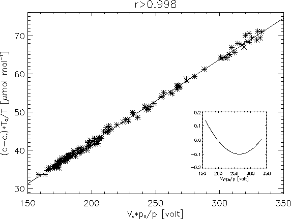
Figure ![]() shows the fit for a typical day. Since most of the variance
is contained in the measured voltage signal it is extremely important to determine
the correct slope of the fits (Berger et al., 2001). Using linear regression,
occasional outliers can result in a poor fit due to an undesired sensitivity
to outlying data, thus they are removed interactively, and the resulting linear
fits typically show very high correlation.
shows the fit for a typical day. Since most of the variance
is contained in the measured voltage signal it is extremely important to determine
the correct slope of the fits (Berger et al., 2001). Using linear regression,
occasional outliers can result in a poor fit due to an undesired sensitivity
to outlying data, thus they are removed interactively, and the resulting linear
fits typically show very high correlation.
The manufacturer provides a fifth order polynomial calibration curve for the
instrument (LI-COR, 1996), but the polynomial differs only slightly from linear
in the range of interest (360-500 ppm) as shown by the inset graph in Fig. ![]() .
Calibration values are determined for each 24 hours of measurement. The calibration
factors are quite stable in time.
.
Calibration values are determined for each 24 hours of measurement. The calibration
factors are quite stable in time.
The calibration can be verified with plotting the daily CO![]() time series
determined from the fast response system together with the CO
time series
determined from the fast response system together with the CO![]() data
at 82 m determined from the profiling system.
data
at 82 m determined from the profiling system.