The data processing technique is very similar to that described in section ![]() .
.
Based on ogive tests described in section ![]() it was
found that 30 min averaging time is appropriate to determine turbulent fluxes
considering the height of the measurements (Foken and Wichura, 1996).
it was
found that 30 min averaging time is appropriate to determine turbulent fluxes
considering the height of the measurements (Foken and Wichura, 1996).
Spectral analysis is performed to check the quality of the measured data.

|
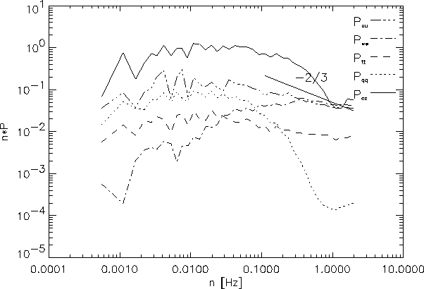
Figure ![]() shows the power spectra of horizontal wind speed,
vertical wind speed, temperature, water vapor and carbon dioxide mixing ratio
as an average of two half hourly spectra measured between 10h and 11h UTC+1
in 19 June, 1999 at 3 m height. The average horizontal wind speed was 3.3 m
s
shows the power spectra of horizontal wind speed,
vertical wind speed, temperature, water vapor and carbon dioxide mixing ratio
as an average of two half hourly spectra measured between 10h and 11h UTC+1
in 19 June, 1999 at 3 m height. The average horizontal wind speed was 3.3 m
s![]() . The plot was chosen to be typical for the whole measurement.
. The plot was chosen to be typical for the whole measurement.
Compared with the power spectra of the 82 m EC system (figure ![]() ),
it is apparent that the temperature spectra is correct here, and all power spectra
behaves well expect the spectra of the IRGA. The spectra of water vapor and
carbon dioxide falls faster in the inertial subrange than the ideal -2/3 slope
which is caused by the signal damping inside the tube, the sensor line averaging
and the limited response time of the instruments. This effect causes more severe
signal loss than at the EC system at 82 m. The increased signal loss is partly
a consequence of the laminar flow configuration inside the tubes (the tube length
is 10 m, the lag time is around 3 sec, and the inner diameter of the tube is
6 mm). As it was stated before (section
),
it is apparent that the temperature spectra is correct here, and all power spectra
behaves well expect the spectra of the IRGA. The spectra of water vapor and
carbon dioxide falls faster in the inertial subrange than the ideal -2/3 slope
which is caused by the signal damping inside the tube, the sensor line averaging
and the limited response time of the instruments. This effect causes more severe
signal loss than at the EC system at 82 m. The increased signal loss is partly
a consequence of the laminar flow configuration inside the tubes (the tube length
is 10 m, the lag time is around 3 sec, and the inner diameter of the tube is
6 mm). As it was stated before (section ![]() ), turbulent flow
field inside the air inlet tube causes less severe signal damping compared to
the laminar case (Lenschow and Raupach, 1991; Massman, 1991; Suyker and Verma,
1993).
), turbulent flow
field inside the air inlet tube causes less severe signal damping compared to
the laminar case (Lenschow and Raupach, 1991; Massman, 1991; Suyker and Verma,
1993).
There is some high frequency noise in the signal of the LI-COR which was also
present in the other EC system. That noise is supposed to be random as it was
stated before (section ![]() ) and is not correlated with the
vertical wind speed.
) and is not correlated with the
vertical wind speed.

|
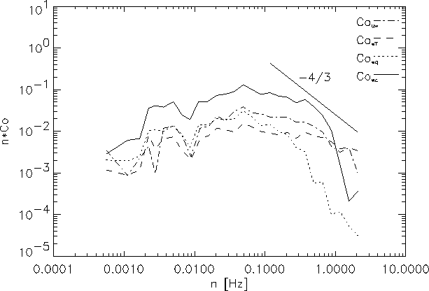
Figure ![]() shows the cospectra of vertical wind speed fluctuations
with horizontal wind speed, temperature, water vapor mixing ratio and carbon
dioxide fluctuations. The plot is constructed as an average of two half hourly
cospectra measured in 19 June, 1999 between 10h and 11h, UTC+1. The average
wind speed was 3.3 m s
shows the cospectra of vertical wind speed fluctuations
with horizontal wind speed, temperature, water vapor mixing ratio and carbon
dioxide fluctuations. The plot is constructed as an average of two half hourly
cospectra measured in 19 June, 1999 between 10h and 11h, UTC+1. The average
wind speed was 3.3 m s![]() .
.
The cospectra of vertical wind speed with the horizontal wind speed behaves
ideally in the inertial subrange as it follows the -4/3 slope. The temperature-vertical
wind speed cospectra exhibits a slight deviation from the ideal shape in the
inertial subrange. The cospectra of water vapor and carbon dioxide drops considerably
faster than the ideal slope. This behaviour was expected from the power spectras.
The degradation is accounted for using spectral correction routines similar
to the one described in section ![]() . It is also evident from
the figure comparing with Fig.
. It is also evident from
the figure comparing with Fig. ![]() that the size of the eddies
that contribute to the turbulent transport is smaller at this height than at
higher elevation in the atmospheric boundary layer. Since spectral degradation
occurs in the high frequency range of the cospectra, it is expected to cause
more severe signal loss than in the case of the 82 m EC system.
that the size of the eddies
that contribute to the turbulent transport is smaller at this height than at
higher elevation in the atmospheric boundary layer. Since spectral degradation
occurs in the high frequency range of the cospectra, it is expected to cause
more severe signal loss than in the case of the 82 m EC system.
Spikes are removed from the time series during data processing (data values
outside ![]() 5
5![]() are removed). The treshold value is somewhat
higher than the one used for the 82 m system, since the low elevation favours
high frequency eddies. Experience shows that in some cases, when wind blows
from the direction of the nearby road, exhaust gas of overpassing cars may cause
short extreme spikes in the carbon dioxide concentration time series which could
cause severe computational error if not accounted for. Other instrument noise
apparent in the wind speed data and sonic temperature data, caused by rime or
liquid water, is also removed. Short before the malfunction of the Kaijo-Denki
sonic anemometer at the beginning of 2001, the system produced extremely noisy
data, mostly present in the sonic temperature time series. During the same period,
the internal temperature and pressure sensor of the IRGA also produced defective
data, and the water vapor signal was also damaged. However, it was still possible
to calculate carbon dioxide fluxes, without the pressure and temperature correction
(see eq.
are removed). The treshold value is somewhat
higher than the one used for the 82 m system, since the low elevation favours
high frequency eddies. Experience shows that in some cases, when wind blows
from the direction of the nearby road, exhaust gas of overpassing cars may cause
short extreme spikes in the carbon dioxide concentration time series which could
cause severe computational error if not accounted for. Other instrument noise
apparent in the wind speed data and sonic temperature data, caused by rime or
liquid water, is also removed. Short before the malfunction of the Kaijo-Denki
sonic anemometer at the beginning of 2001, the system produced extremely noisy
data, mostly present in the sonic temperature time series. During the same period,
the internal temperature and pressure sensor of the IRGA also produced defective
data, and the water vapor signal was also damaged. However, it was still possible
to calculate carbon dioxide fluxes, without the pressure and temperature correction
(see eq. ![]() and eq.
and eq. ![]() ). The quality of the data is reduced
during this period, which should be kept on mind during data interpretation.
). The quality of the data is reduced
during this period, which should be kept on mind during data interpretation.
Three dimensional wind vector rotation is applied to the sonic anemometer data to ensure that the mean vertical velocity equals to zero (McMillen, 1988). The method is mainly used to account for the shadow effect of the sonic head. No significant real average vertical wind speed is expected to occur at this height (Lee, 1998).
A linear trend is removed from each half hourly (or 16 min long, before 13 April, 1999) time series to calculate the fluctuating time series.
Lag times are determined during the data processing using spectral technique. The lag times are considerably smaller in this case since the air inlet tube is much shorter here.
Turbulent fluxes are calculated from covariances of the despiked and detrended
time series taking into account the delay time of the signals. Raw covariances
are converted into physical quantities using equations ![]() -
-![]() .
.
Spectral corrections are applied to account for the damping of the signal inside
the tube, the sensor line averaging, the limited response time of the anemometer
and the IRGA, and the analogue-to-digital conversion. The methodology of the
correction is described in subsection ![]() . The neccessary
parameters are as follows: the separation distance between the air inlet and
the anemometer is 23 cm, the response time of the Kaijo-Denki sonic anemometer
is 0.1 sec, the response time of the LI-6262 is 0.1 sec, the path length of
the anemometer is 20 cm, the length of the teflon tube is 10 m and the inner
diameter is 6 mm.
. The neccessary
parameters are as follows: the separation distance between the air inlet and
the anemometer is 23 cm, the response time of the Kaijo-Denki sonic anemometer
is 0.1 sec, the response time of the LI-6262 is 0.1 sec, the path length of
the anemometer is 20 cm, the length of the teflon tube is 10 m and the inner
diameter is 6 mm.

|
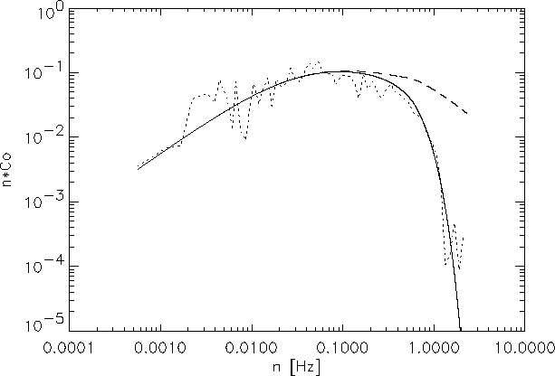
Figure ![]() shows the cospetra of the vertical wind
speed fluctuations with the carbon dioxide mixing ratio fluctuations measured
in 20 June, 1999 between 10h and 11h UTC+1 together with the theoretical Kaimal
cospectra for unstable situations, and the same cospectra multiplied by the
total measuring system transfer function. The average horizontal wind speed
was 3.3 m s
shows the cospetra of the vertical wind
speed fluctuations with the carbon dioxide mixing ratio fluctuations measured
in 20 June, 1999 between 10h and 11h UTC+1 together with the theoretical Kaimal
cospectra for unstable situations, and the same cospectra multiplied by the
total measuring system transfer function. The average horizontal wind speed
was 3.3 m s![]() . The measured cospectra follows the simulated one well
indicating that the theoretical transfer functions describe the behaviour of
the system adequately. This result also supports the validity of the spectral
corrections applied to the EC system at 82 m, where the validity of the correction
is less confirmed visually.
. The measured cospectra follows the simulated one well
indicating that the theoretical transfer functions describe the behaviour of
the system adequately. This result also supports the validity of the spectral
corrections applied to the EC system at 82 m, where the validity of the correction
is less confirmed visually.
Figure ![]() shows the relative frequency distribution of the
CO
shows the relative frequency distribution of the
CO![]() flux loss calculated from the theoretical considerations. The
histogram was cproduced using all available data.
flux loss calculated from the theoretical considerations. The
histogram was cproduced using all available data.
Average losses of the eddy covariance system are about 23.1% for CO![]() and 20.4% for H
and 20.4% for H![]() O. In 75.1% of the cases for H
O. In 75.1% of the cases for H![]() O and in
79.7% for CO
O and in
79.7% for CO![]() the loss is between 10% and 30%.
the loss is between 10% and 30%.
Additionally, Obukhov length is calculated from the turbulent characteristics and stored to provide stability information neccessary for the spectral corrections and for the flux source area analysis.