It is not possible to construct a measuring system which detects all fluctuations with zero response time, and wich does not affect the measured signal itself. Moreover, introducing a closed-path gas analyzer to the system causes extra demands with regards to corrections. A part of these corrections -- e.g. the utilization of the lag time -- was already described.
Spectral corrections are supposed to be applied in order to account for the damping of fluctuations caused by the long air sample tubes, limited sensor response time, sensor line averaging and sensor separation, and sampling. One possible correction method is the application of a series of transfer functions defined for each correction term (Moore, 1986; Leuning and Moncrieff, 1990; Lenschow and Raupach, 1991; Massman, 1991; Leuning and King, 1992; Suyker and Verma, 1993; Moncrieff et al., 1997; Aubinet et al., 2000).
One other scheme which is quite frequently used in micrometeorology is the application
of the spectral corrections based on the comparison of the (hopefully) ideally
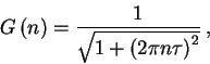
measured sensible heat cospectra (Co![]() , see e.g.
, see e.g. ![]() for the
definition of cospectra), and the degraded water vapor and carbon dioxide cospectra
(Högström et al., 1989; Grelle, 1997; Berger et al., 2001). The method
is quite attractive, however it is not to apply to our system since the temperature
signal is heavily degraded. Both method is based on the assumption of spectral
similarity between temperature, H
for the
definition of cospectra), and the degraded water vapor and carbon dioxide cospectra
(Högström et al., 1989; Grelle, 1997; Berger et al., 2001). The method
is quite attractive, however it is not to apply to our system since the temperature
signal is heavily degraded. Both method is based on the assumption of spectral
similarity between temperature, H![]() O and CO
O and CO![]() (Anderson and
Verma, 1984; Ohtaki, 1985).
(Anderson and
Verma, 1984; Ohtaki, 1985).
The scheme of Moore (1986) is applied through the use of transfer functions for each correction term. The fractional error of the measured flux can be written as:
To calculate
![]() , we need to determine each individual
transfer functions. In our system, corrections are applied in order to take
into account the effect of the signal damping inside the air inlet tube, the
limited time response of the IRGA, the sensor line averaging inside the IRGA's
optical path, the sensor line averaging caused by the sonic anemometer, the
sensor separation caused by the separation of the sensors (i.e. the separation
of the air inlet and the sonic anemometer), and the effect of the discretized
sampling of the continuously fluctuating flow field (Moore, 1986). These transfer
functions are described in the followings.
, we need to determine each individual
transfer functions. In our system, corrections are applied in order to take
into account the effect of the signal damping inside the air inlet tube, the
limited time response of the IRGA, the sensor line averaging inside the IRGA's
optical path, the sensor line averaging caused by the sonic anemometer, the
sensor separation caused by the separation of the sensors (i.e. the separation
of the air inlet and the sonic anemometer), and the effect of the discretized
sampling of the continuously fluctuating flow field (Moore, 1986). These transfer
functions are described in the followings.
a) Spectral attenuation
The signal damping (i.e. spectral attenuation) caused by the long air inlet tubes can be approximated if the type of the flow (laminar or turbulent) is known and the parameters of the tubing are measured (Leuning and Moncrieff, 1990; Massman, 1991; Leuning and King, 1992; Moncrieff et al., 1997; Suyker and Verma, 1993). Caused by the change in the lag time of our eddy covariance system, the type of the flow is not constans in time, but dependent on the date. Massman (1991) provides transfer functions for both laminar and turbulent flow rates.
The general transfer function has the form of
In case of laminar flow rate (
![]() 2300,
where the kinematic viscosity of air is calculated as
2300,
where the kinematic viscosity of air is calculated as
![]() m
m![]() s
s![]() ,
with the air temperature
,
with the air temperature ![]() in Celsius), the tube attenuation coefficient
can be written as (Philip, 1963):
in Celsius), the tube attenuation coefficient
can be written as (Philip, 1963):
In case of turbulent flow inside the sampling tube Massman (1991) provides values
of ![]() and minimum
and minimum ![]() values for different Reynolds numbers
(Table 1. in Massman's paper). Practically, the attenuation coefficient is determined
with interpolation using the data provided by Massman (1991) for any given Reynolds
number.
values for different Reynolds numbers
(Table 1. in Massman's paper). Practically, the attenuation coefficient is determined
with interpolation using the data provided by Massman (1991) for any given Reynolds
number.
Comparison of the transfer functions associated with laminar and turbulent flow shows that turbulent flow field inside the air inlet tube causes less severe signal damping compared to the laminar case (Lenschow and Raupach, 1991; Massman, 1991; Suyker and Verma, 1992), hence this configuration is the desirable in eddy covariance systems using long air inlet tubes.
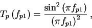
b) Limited time response of the IRGA
The transfer function associated with the limited time response of the LI-COR
6262 IRGA (![]() =0.1 sec, Moncrieff et al., 1997) has the following form
(Moore, 1986; Moncrieff et al., 1997):
=0.1 sec, Moncrieff et al., 1997) has the following form
(Moore, 1986; Moncrieff et al., 1997):
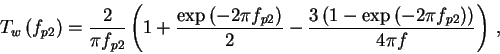
c) Line averaging
If a sensor measures the turbulent flow field over a finite sampling path, the signal of turbulent eddies with size comparable with the sensor path is averaged. In order to take it into account transfer functions should be applied. This function has a different form for scalar and vector quantities (Moore, 1986).
In our system, the LI-COR 6262 IRGA has an optical path with a length of 15.2 cm.
To take into account its line averaging effect, the following transfer function
should be considered:
A different transfer function is applied to the sonic anemometer data which
has a transducer head-to-head averaging path of 15 cm. According to Moore (1986),
this function is as follows:
d) Sensor separation
The sensor separation can be hadled using the general transfer function for
lateral and longitudinal sensor separation (Moore, 1986). The transfer function
has the form of
e) Discretized sampling
The effect of the discretized sampling of the continuously fluctuating flow
field using the analog to digital conversion can be approximated using the following
equation (Moore, 1986):
The whole data acquisition system's transfer function can be calculated utilizing
all transfer functions described above (subscript ![]() refers to CO
refers to CO![]() or H
or H![]() O):
O):
Note that the only difference between the whole system's transfer function for
CO![]() and H
and H![]() O resides in the different signal damping inside
the air inlet tubes described by the different transfer functions, which is
caused by the different molecular diffusivity (
O resides in the different signal damping inside
the air inlet tubes described by the different transfer functions, which is
caused by the different molecular diffusivity (![]() ) values for water vapor
and carbon dioxide in eq.
) values for water vapor
and carbon dioxide in eq. ![]() and
and ![]() .
.
In an earlier stage of the data processing moving averages trend removal technique
was applied, which needed further spectral correction described by Kaimal et
al. (1968). As it was described in section ![]() , linear
trend removal is applied currently, which does not cause spectral modification
of the turbulent characteristics.
, linear
trend removal is applied currently, which does not cause spectral modification
of the turbulent characteristics.
Once the system's transfer function is determined, we have to obtain adequate
cospectral models which can be applied in eq. ![]() to estimate the loss
in the system. The modified forms of model spectra of Kaimal et al. (1972) is
used for this purpose (Moore, 1986, Moncrieff et al., 1997). These normalized
model spectras describe the stability dependent behaviour of the atmospheric
spectra and cospectra of wind speed, temperature or any other scalar. The integrals
of the model cospectra are equal to unity, thus they can easily be modified
to simulate the real atmospheric spectra of the parameter in question.
to estimate the loss
in the system. The modified forms of model spectra of Kaimal et al. (1972) is
used for this purpose (Moore, 1986, Moncrieff et al., 1997). These normalized
model spectras describe the stability dependent behaviour of the atmospheric
spectra and cospectra of wind speed, temperature or any other scalar. The integrals
of the model cospectra are equal to unity, thus they can easily be modified
to simulate the real atmospheric spectra of the parameter in question.
The model spectra definitions are based on the normalised frequency
![]() ,
where
,
where ![]() is the measuring height above the zero plane displacement
is the measuring height above the zero plane displacement ![]() ,
and
,
and ![]() is the average horizontal wind speed. Normalization is neccessary
since high wind speed causes the turbulent signal biased towards the higher
frequency range accorning to Taylor's hypothesis (Stull, 1988).
is the average horizontal wind speed. Normalization is neccessary
since high wind speed causes the turbulent signal biased towards the higher
frequency range accorning to Taylor's hypothesis (Stull, 1988).
The functional forms of the model spectra are as follows. During stable conditions
it is written as
During unstable conditions the model spectras are as follows:
As it was mentioned at the end of subsection ![]() , Obukhov length
is calculated in each hourly period to provide stability information for the
model spectra calculations. Flux loss caused by the eddy covariance system is
estimated substituting the model cospectra and the overall system transfer function
into
, Obukhov length
is calculated in each hourly period to provide stability information for the
model spectra calculations. Flux loss caused by the eddy covariance system is
estimated substituting the model cospectra and the overall system transfer function
into ![]() .
.
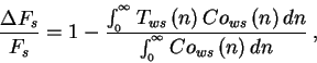
Since the manipulation described above are based on theoretical transfer functions published in the literature, it is useful to prove that the cospectra behaves the same way as it is expected.
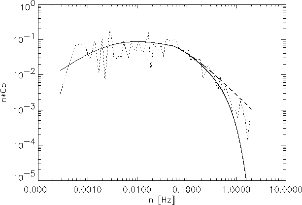
|
Figure ![]() shows the cospectra of the vertical wind
speed fluctuations with the carbon dioxide mixing ratio fluctuations measured
in 5 August, 1998 between 10h and 12h UTC+1 together with the theoretical Kaimal
cospectra for unstable situations, and the same cospectra multiplied by the
total measuring system transfer function. The average horizontal wind speed
was 8.2 m s
shows the cospectra of the vertical wind
speed fluctuations with the carbon dioxide mixing ratio fluctuations measured
in 5 August, 1998 between 10h and 12h UTC+1 together with the theoretical Kaimal
cospectra for unstable situations, and the same cospectra multiplied by the
total measuring system transfer function. The average horizontal wind speed
was 8.2 m s![]() . The measured cospectra follows the simulated one well
indicating that the theoretical transfer functions describe the behaviour of
the system adequately. There is a slight deviation from the theoretical curve
at the highest frequencies, but the contribution of the shortest wavelengths
to the total flux is very little (e.g. the area under the curve at that specific
interval is little).
. The measured cospectra follows the simulated one well
indicating that the theoretical transfer functions describe the behaviour of
the system adequately. There is a slight deviation from the theoretical curve
at the highest frequencies, but the contribution of the shortest wavelengths
to the total flux is very little (e.g. the area under the curve at that specific
interval is little).
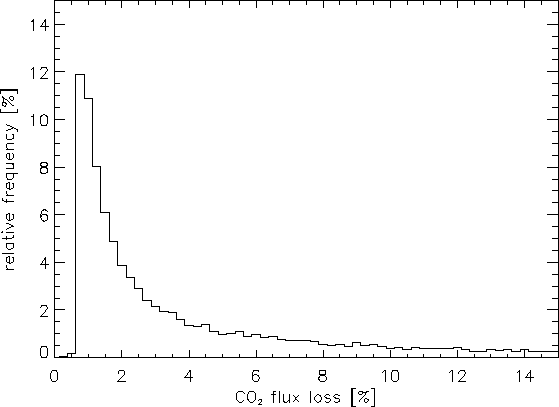
Figure ![]() shows the relative frequency distribution of the CO
shows the relative frequency distribution of the CO![]() flux loss calculated from the theoretical considerations. The histogram was
created using all available data.
flux loss calculated from the theoretical considerations. The histogram was
created using all available data.
Average losses of the eddy covariance system are about 6.6% for CO![]() and 5.9% for H
and 5.9% for H![]() O. In 59% of the cases for H
O. In 59% of the cases for H![]() O and in 55%
for CO
O and in 55%
for CO![]() the loss is less than 3%. In 84% of the cases for H
the loss is less than 3%. In 84% of the cases for H![]() O
and in 82% for CO
O
and in 82% for CO![]() the loss is less than 10%. Flux loss is higher
during stable conditions. Low values of the Obukhov length (
the loss is less than 10%. Flux loss is higher
during stable conditions. Low values of the Obukhov length (![]() , defined
by eq.
, defined
by eq. ![]() ) or high wind speed conditions (
) or high wind speed conditions (![]() ), cause extra loss.
For example,
), cause extra loss.
For example, ![]() =10 m and
=10 m and ![]() =5 m s
=5 m s![]() causes 21.7% and
23.4% loss for H
causes 21.7% and
23.4% loss for H![]() O and CO
O and CO![]() , respectively. In case of
, respectively. In case of ![]() =20
m and
=20
m and ![]() =15 m s
=15 m s![]() , the loss is 26.4% for H
, the loss is 26.4% for H![]() O and
29.5% for CO
O and
29.5% for CO![]() .
.
As it was mentioned before, it appears that the water vapor signal suffers from excess spectral degradation compared to the theoretical spectral damping because of the long tubing of the system which causes extra loss of water vapor flux, hence needs more investigation, but this is out of scope of this work.
![\begin{displaymath}
A_{ws}=0.284\left[ 1+6.4\left( \frac{z-d}{L}\right) \right] ^{0.75}\: ,
\end{displaymath}](img230.gif)